In this post, I will explain an example of batch firmware download and operation testing for five WIZ750SR modules from WIZnet using the testX Flasher and a single interface board.
First, you need to know the pinout of the WIZ750SR module in order to configure the connection with the testX Flasher.
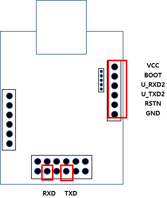
WIZ750SR Module Pinout
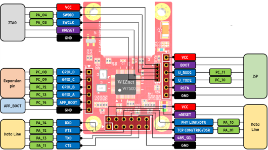
(source: https://docs.wiznet.io/Product/S2E-Module/WIZ750SR/datasheet)
As shown in the diagram, many pins are provided, but the pins related to firmware download are the power (VCC, GND), BOOT, RSTN, U_RXD2, and U_TXD2, totaling six pins. Additionally, to verify that the firmware operates correctly after the download, the RXD and TXD pins for data communication are also used.
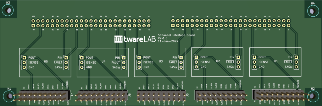
testX Flasher Interface board Pinout
To easily connect the testX Flasher TWF-100 with the user's target board, Twarelab offers the testX Flasher Interface board as an option.
For detailed specifications, please refer to the separate document.
The interface board provides connectors for connecting five target boards, and the connectors for the target boards have the following pinout.
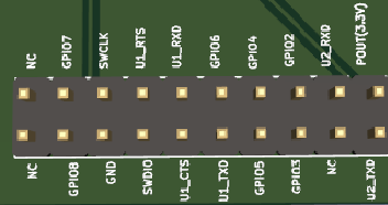
| Pin No. | Pin Name | Direction | Remarks |
| 1 | POUT(3.3V) | PWR | |
| 2 | U2_TXD | OUT | |
| 3 | U2_RXD | IN | |
| 4 | NC | NA | |
| 5 | GPIO2 | IN/OUT | |
| 6 | GPIO3 | IN/OUT | |
| 7 | GPIO4 | IN/OUT | |
| 8 | GPIO5 | IN/OUT | |
| 9 | GPIO6 | IN/OUT | |
| 10 | U1_TXD | OUT | |
| 11 | U1_RXD | IN | |
| 12 | U1_CTS | IN | |
| 13 | U1_RTS | OUT | |
| 14 | SWDIO | NA | |
| 15 | SWCLK | NA | |
| 16 | GND | PWR | |
| 17 | GPIO7 | IN/OUT | |
| 18 | GPIO8 | IN/OUT | |
| 19 | NC | NA | |
| 20 | NC | NA |
Pin connections between the Interface board and the Target board
- The ISP (In-System Programming) port of the W7500(P) MCU used in the WIZ750SR is connected to U2_RXD and U2_TXD. Connect it to one of the UART ports on the Interface board.
- Connect the BOOT pin and RSTN pin of the WIZ750SR to the GPIO pins on the Interface board.
- Connect the RXD and TXD pins for data transmission and reception to another UART port on the Interface board.
According to the above criteria, the pin connections are as follows.
| Interface board | WIZ750SR |
| POUT(3.3V) | VCC |
| GPIO5 | BOOT |
| U2_TXD | U_RXD2 |
| U2_RXD | U_TXD2 |
| GPIO6 | RSTN |
| GND | GND |
| U1_TXD | RXD |
| U1_RXD | TXD |
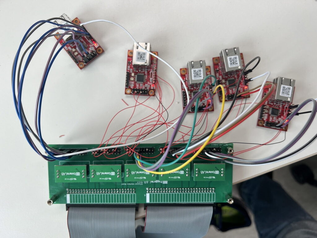
Below is an actual setup where the WIZ750SR and the interface board are connected using jumper cables and wrapping cables.
Test Procedure (Test Set)
- Power on the WIZ750SR via control of the eFuse module on the interface board.
- Reset the WIZ750SR using control of the RSTN pin.
- Enter W7500 Boot Mode by controlling the BOOT and RSTN pins.
- Erase existing data in the flash memory.
- Download the specified firmware.
- Reboot using control of the RSTN pin
- Check the messages coming from the WIZ750SR U_TXD2 pin using U2_RXD to verify if it is booting correctly.
- Send AT commands to the WIZ750SR using U1_TXD.
- Check the responses from the WIZ750SR using U1_RXD.
If there is a response timeout or if the expected value is not received at any step in the procedure, consider it a failure.
Demonstration Video
Here is a demonstration video of the procedure described above.
0 Comments