When working with microcontrollers (MCUs), one of the most common tasks is enabling communication between devices. Among the available options—UART, I²C, and SPI—SPI (Serial Peripheral Interface) stands out for its speed and simplicity.
Typically, SPI communication involves a microcontroller acting as the Master and a dedicated IC functioning as the Slave. The Master generates the clock signal, and the Slave synchronizes to this clock to either send or receive data. This arrangement works seamlessly when the Slave is a specialized IC with hardware logic designed for SPI.
However, things become more complicated when two MCUs need to talk to each other over SPI. Each MCU is busy running its own application tasks, making it difficult to rely on the conventional SPI mechanism without running into blocking calls, resource contention, or data loss.
In this article, I’ll walk you through why this problem arises, what requirements must be met, and how we designed a practical solution using a dual-SPI setup with DMA.
Why Not Just Use UART?
One might suggest simply using UART for MCU-to-MCU communication.
While UART is widely supported and easy to use, in our case, all UART ports on both devices were already reserved for other functions. That meant UART was not an option, leaving us with SPI as the most viable path forward.
Requirements for a Robust SPI Solution
When defining the communication method, we had to meet several important requirements:
- Each device must continue running its own tasks without interruption.
- The SPI link must be non-blocking, avoiding scenarios where one device waits indefinitely for data.
- Data transfers should be as fast as possible.
- - No data loss can be tolerated, even under heavy workloads.
The Design Approach
To achieve these goals, we implemented a dual-SPI configuration:
- Two SPI ports are used—one dedicated to transmitting and the other to receiving.
- Each port operates in Half Duplex mode.
- The Master port handles transmission only.
- The Slave port handles reception only.
- DMA (Direct Memory Access) is employed to offload data transfers from the CPU, ensuring minimal MCU resource usage and avoiding bottlenecks.
이 방식은 MCU 리소스를 절약하면서도 빠르고 안정적인 데이터 교환을 가능하게 합니다.
Detailed Implementation
The figure below shows the conceptual block diagram of the implementation.
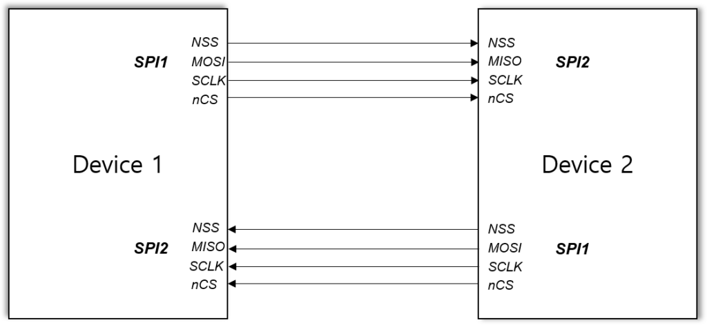
To ensure synchronization and data integrity, we introduced two control signals per SPI channel: NSS and nCS.
- NSS (Hardware-controlled): Provides timing synchronization for SPI communication.
- nCS (Software-controlled): Acts as a frame delimiter, indicating when a data frame begins and ends during DMA transfers.
Master Side
- Configure nCS as a GPIO output.
- Before transmitting data, drive nCS Low.
- When the DMA transfer is complete (signaled by the Tx Complete interrupt), set nCS High again.
Slave Side
- Configure nCS as a GPIO input with EXTI interrupt capability.
- On the Falling Edge, mark the start of a receive frame (Rx Start flag).
- On the Rising Edge, mark the end of the frame (Rx Complete), then move the received data from the DMA buffer into the application buffer for processing.
This division of roles keeps the communication non-blocking, synchronized, and efficient.
Test Results
In real-world testing, the system handled substantial workloads without data loss. Specifically, we successfully exchanged:
- 7 UART channels worth of data,
- 24 GPIO control signals, and
- 18 streams of sensor data
all in real time and without any issues.
Summary
Establishing reliable communication between two MCUs over SPI is not as straightforward as connecting an MCU to a dedicated IC. By carefully designing the communication scheme—using dual SPI channels, DMA transfers, and additional control signals—it is possible to achieve fast, non-blocking, and lossless data exchange.
This approach has proven effective in demanding scenarios where multiple data streams must be handled concurrently, and it provides a solid foundation for robust MCU-to-MCU communication in embedded systems.
0 Comments